
ONE-CRIMP And Chip Breaking
In the metal cutting process, the lousy chip shape affects the operation safety, the processing quality, the tool life, machine accuracy, and productivity.
Therefore, it is necessary to study the chip curling form and chip breaking method to control the chip shape effectively.
- Chip curl form
In the plastic metal cutting process, due to the different degree of chip upward curling and lateral curling, the resulting chip patterns are also different. Facilitate the analysis of chip crimp patterns;
chips may be divided into UPWARD CRIMP type, compound CRIMP type, and transverse CRIMP type.
In Brittle metal cutting, Granular easy chips and needle chips are produced only in high-speed cutting; the tool rake angle is large, cutting thickness is small.
The curling direction of this kind of chip is slightly different from that of the general case.
When cutting plastic metal, such as tool edge inclination angle is 0°, there is a chip groove, and cutting width is more massive, chip mostly was curled up. In other cases, the chips are mostly horizontally curled.
For example, in cylindrical turning, when the amount of feed and back to eating a more massive amount of knife, and the tool rake angle When the chip is 0, it is easy to curl horizontally into a Washer (see figure 1).

It is because the two ends of the chip are transverse
Up The width, and the chip volume unchanged, the width of the transverse part of the thickness must be thinner if the length is not shortened.
Also, if there is a transition edge on the turning tool, the tooltip and the sub-cutting border are added.
The role of the chip width in the direction of shear angle changes, but also can cause the chip lateral bending and
In the shape of a gasket. In general, the chip can not be curled only upward or laterally, but upward
Lateral CRIMP is also produced when CRIMP. The formation of long, tight and spiral coils is the simultaneous upward and upward movement of the chips
The result of the lateral curl (figure 2).
- Chip breaking
In plastic metal cutting, straight strip chips and winding chips are not welcome; in Brittle Gold
Belong to cutting, and want to get the continuous chip. In general, changing the cutting parameters or tool geometry can
Control chip. The chip-breaker and chip-breaker used in the processing of plastic metal under the condition that the cutting parameters fixed the roll-chip slot controls the chip shape.
According to the Mechanical Analysis:
(1) the smaller the yield limit of the material to cut, the lower the elastic recovery and the easier it is to break;
(2) when the elastic modulus of the material cut is large, it is also easy to break;
(3) the lower the plasticity of the material cut, the easier it is to break;
(4) the more significant the cutting thickness, the higher the strain, the easier it is to break, and the thin chip is hard to break;
(5) the back eat knife quantity increases, then breaks the chip difficulty to increase;
(6) the chip breaking effect decreases with the addition of cutting speed;
(7) the smaller the tool rake angle, the larger the chip deformation, and the easier it is to break.
The following diagram shows three common chip-rolling groove forms: LINEAR (a), LINEAR ARC (b), and Full Arc (c).
Straight and straight ARC type chip winding groove is suitable for cutting carbon steel, structural alloy steel, tool steel.
General Rake Angle 5°-15 °range.
FULL-ARC CHIP-WINDING GROOVE is suitable for cutting high plastic materials such as copper and stainless steel. Its rake angle can increase to 25°-30 °range.

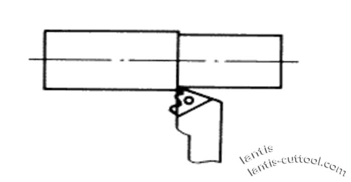
TWO-Cutting Force
- sources of cutting forces and their decomposition
Study of cutting force, to further clarify the cutting mechanism, to calculate the power consumption, to the tool, machine tool,
the design of the fixture is crucial for making reasonable cutting parameters and optimizing the geometric parameters of cutting tools The meaning of the word.
In metal cutting, the tool cuts into the workpiece, causing the material to deform and become the force required for the chip Called the cutting force.
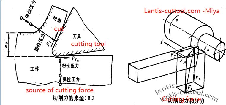
The CUTTING FORCE COMES FROM THREE SOURCES:
- Overcome the resistance of processed materials to elastic deformation;
- Overcome the strength of the processed material to plastic deformation;
- Overcome the friction between the chip and the rake face and the transition surface between the tool and the back face
The conflict between the covers.
The sum of the above forces forms the resultant force Fr (F) acting on the tool. For practical purposes,
fr can decompose into three perpendicular Fx (national standard Ff), Fy (National Standard Fp), and Fz (National Standard Fc).
Component Force. In Turning:
Fz– cutting or tangential force. It is tangent to the transition surface and perpendicular to the base. Fz Is used to calculate the strength of the turning tool
To design machine tool parts and determine the necessary machine tool power.
Fx power, axial force, or cutting force. It is in the base plane and parallels to the axis of the workpiece with the tool
Opposite effects. Fx is necessary to design the tool feed mechanism and calculate the feed power of the turning tool.
Deep Resistance, or back force, radial force, knife force. It is in the base plane and connected with the workpiece shaft Vertical Force of line.
Fy is used to determine the workpiece accuracy related to the deflection of the workpiece, computer machine parts, and lathe knife strength. It is associated with the vibration of the workpiece in the cutting process.
The power consumed in the cutting process is called the cutting power Pm (Po). Cutting Power Fz and the sum of the energy consumed by Fx, no power is wasted because there is no shift in the Fy Direction. And so.
Pm=(FzV+Fxnwf/1000)×10-3
Among them: Pm -Cutting Power (KW) ;
Fz — Cutting Force (N) ;
V — Cutting Speed (m / s) ;
Fx–Feeding Force(N) ;
Speed of workpiece (r / s) in nw ;
f –feeding (mm / s).
The second term on the right side of the equals sign is the power consumed in the feed motion relative to the energy consumed by F
In general, it is tiny (1% ~ 2%) and can be omitted, so Pm=FzV×10-3
After calculating the cutting power according to the formula above, if you want to calculate the ability of the machine motor PE to select machine electricity
The motive should also take into account the machine tool transmission efficiency.
PE≥ Pm/ηm
In the formula: The transmission efficiency of the Nm-type machine tool is generally 0.75 ~ 0.85; the tremendous value is suitable for the new machine tool, the small amount appropriate for used machine tools.
Cutting Force And Testing
Factors Affecting the Cutting Force
-
The influence of the processed material
The physical and mechanical properties, chemical composition, heat treatment state of the material to be processed, and the addition of the material before cutting The working state affects the cutting force.
In general, the higher the strength and hardness of the processed parts, the higher the cutting force. But cutting The magnitude of the power is not only affected by the original power and hardness of the material, but also by the work hardening ability of the material
Size effects. Such as stainless steel and high-temperature alloy materials, its strength and hardness are not high, but the strengthening system A large number of smaller deformation will lead to a significant increase in hardness, thus increasing the cutting force.
The chemical composition will affect the physical and mechanical properties of the material, thus affecting the size of the cutting force. As in carbon steel
The amount of carbon content, whether or not the alloy elements will affect the strength and hardness of steel, thus affecting the cutting Force.
When processing cast iron and other brittle materials, the plastic deformation of the chip layer is minimal, and the work hardening is small. Also,
brittle materials, such as cast iron, form crumbled chips when they cut, and the chips concentrated in the contact between the tip and the front face of the tool
Small area, small friction. Therefore, the cutting force of cast iron is less than that of steel.
-
Cutting quantity cutting force
- As the depth of cut ap increases, the cutting area increases in direct proportion, which increases the deformation force and the friction force
And the cutting power also increases, and the cutting force is proportional to the depth of cutting;
2. feed f increases, cutting area, is comparable to improve, so that the deformation force increases, friction force increases, so
The cutting force increases with it. However, as feed F increases, the cutting thickness AC f · Sin Kr also increases in direct proportion
The deformation Coefficient reduced, the friction also overcame, and the cutting force reduced. The results are both positive and negative
So that the increase of cutting power and feed F is not proportional to the rise.
It can conclude that working with a large feed rate F is more advantageous than working with tremendous cutting depth.
3. When processing the materials such as cast iron, the plastic deformation is small, and the friction between the chip and the front surface of the tool is low.
The force is small, so the cutting speed has little effect on the cutting force.
Processing of steel parts and other plastic deformation of materials, as a result of the formation and disappearance of debris, so that the tool As the actual rake angle increases and decreases, the cutting force increases with the growth of cutting speed.
Again Reduce (the accumulation of debris tumor disappear). When there is no chip accretion, the cutting force decreases with the increase of cutting speed.
Influence of cutting geometric tool parameters on cutting force
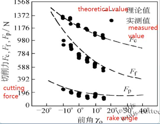
- The effect of Rake Angle on reducing power
When machining steel parts, the cutting force decreases with the increase of Rake Angle
It decreases with the rise of cutting speed
When Processing Brittle materials such as cast iron and bronze, because chip deformation and work hardening is minimal, so before The effect of angle on cutting force is not significant.
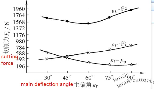
- The impact of Main deflection angle on cutting power
(1) when the cutting area is invariable, the central deflection angle increases, the cutting thickness also increases, the chip thickens, the cutting
The deformation of the cut layer will decrease, so the main cutting force Fc also decreases with the increase of the central deflection angle, but when the principal deflection angle increases
At 60°- 70°, Fc increases gradually
(2) the back force Fp decreases with the growth of the primary deflection angle, while the feed force Ff rises with the increase of the maximum deflection angle Big.
Leave A Comment