
1. Introduction of different cutting tool materials
The main range of cutting tool materials
- Uncoated cemented carbide (HW)
- Coated Cemented Carbide (HC)
- CERMET (HT, HC)
- Ceramics (CA, CN, CC)
- Cubic Boron NITRIDE (BN)
- Polycrystalline diamond (DP, HC)
– Hw non-coated cemented carbide containing mainly tungsten carbide WC.
– HT non-coated cemented carbide, also known as Cermet, mainly includes TIC or TIN or both.
– HC above cemented carbide, but with coating.
– Ca Oxide ceramics, mainly containing alumina Al2O3.
– CM composite ceramics containing mainly alumina Al2O3 but also other components in addition to oxides.
– CN nitride ceramics, mainly containing silicon nitride Si3N4.
– CC above ceramic, but coated.
–D P polycrystalline diamond
– BN CUBIC Boron nitride
Polycrystalline diamond and cubic Boron nitride are also known as superhard cutting tool materials
 Unsintered hard coating
Material characteristics, functions, advantages, and disadvantages
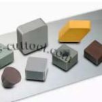
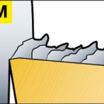
• The 45-face milling inserts shown before sintering, before covering and after layer,
• For medium to demanding applications related to steel, HRSA, titanium, cast iron, and Non-ferrous metal in turning, milling, and drilling.
Excellent combination of abrasion resistance and extraordinary toughness.
• Come with a sharp cutting edge.
• Outstanding cutting edge safety, but limited wear resistance at high speeds.
• Represents a small portion of the entire material product line.
 Sintered cemented carbide as a coating
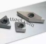
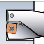
• above, one of Lantis’s main products, ONEX090510TN-F10, focuses on milling of sticky materials.
• Conventional for turning, milling, and drilling applications of various parts and materials.
Excellent combination of abrasion resistance and toughness for all types of work.
• Includes a large number of substrates from hard to severe, usually sintered using a gradient, with a variety of CVD and PVD coatings.
• Exhibits excellent wear resistance and long tool life.
• Dominate the blade product line, and its share is growing.
 CERMET
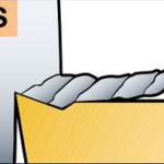
• For finish and semi-finish applications requiring high tolerances and excellent surface quality.
• Chemically stable with a hard, abrasion-resistant Matrix.
• Sintered hard metals, including titanium-based TiC and TiCN, use cobalt as an adhesive.
PVD coating improves wear resistance and extends tool life. “self-sharpening” feature. Limited toughness.
• A relatively low share in the overall blade product line.
 Ceramics
• These materials are mainly used for cast iron, steel, hard plastics, and HRSA, depending on the type of ceramics.
• Ceramic materials are generally wear-resistant and have excellent thermal hardness. Wide range of applications, suitable for different kinds of materials and parts.
• Ceramics are considered fragile and therefore require stable working conditions. The toughness of the ceramics improved by the addition of the whisker and the mixture.
• A relatively low share of total blade usage, but increased use in aerospace and hardened steel-cast iron applications.
 Cubic Boron nitride
• Used for finishing hardened steel, roughing gray cast iron at high cutting speeds, and white finishing
/ chilled cast iron roll roughing.
• Applications require a high degree of wear resistance and toughness.
• CBN includes Boron nitride tape ceramic or titanium nitride adhesives.
• Resistant to high cutting temperatures at high cutting speeds.
• Specific applications where a small number of blades are used. The trend is towards cutting more quantities of hard material.
 Polycrystalline diamond
• The low-temperature turning of conventional Non-ferrous metal and turning of extremely Abrasive hyper eutectic Non-ferrous metal. For processing non-metallic and Non-ferrous metal materials.
• The material is exceptionally resistant to wear. Disintegrating Blade.
• Fillet-welding polycrystalline diamond PCD tooltips onto the blade or thin diamond-coated films onto the substrate.
• Long tool life and excellent wear resistance. It decomposes quickly at high temperatures. Soluble in iron.
• The share in the blade product line is quite low and is usually limited in the area of specialization.
2. Introduction to six categories of materials
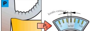
Class P-STEEL
• What is steel?
– Steel is the largest group of elements in the field of metal cutting.
– Steel may be non-hardened steel or quenched and tempered steel with hardness up to 400hb.
– Steel is an alloy of iron and FE. It’s made by a smelting process.
– non-alloy steel has a carbon content of less than 0.8% and contains only Fe and no other alloying elements.
The carbon content of-alloy steel is less than 1.7%, and alloy elements such as NI, CR, Mo, v, W added.
• processing characteristics:
– long chip material.
– Chip Control is relatively easy and smooth.
– Low Carbon Steel is viscous and requires a sharp cutting edge.
– CUTTING FORCE KC: 1500 something 3100 N / MM2.
– The cutting force and power needed to process ISO p materials are within a limited range.
– Milling with Etna PM2511 / PM2022 brand.
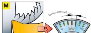 Class M-STAINLESS steel
• What is stainless steel?
– stainless steel is an alloy with a minimum of 11 something 12% chromium.
– Carbon content is usually shallow to a maximum of 0.01%.
– Alloys are mainly Ni, Mo, Mo, and TI.
– forming a dense layer of Cr2O3 on the steel surface to make it resistant to corrosion.
• processing characteristics:
– long chip material.
– Chip Control is relatively smooth in ferrite and difficult in austenite and BIPHASIC.
– Cutting force per unit: 1800-2850N / MM2.
– produces high cutting force, build-up, heat, and work hardening during machining.
– Milling with Etna MP3011 / PM2012 / SM3523.
 Class K-CAST IRON
• WHAT IS CAST IRON?
– cast iron comes in three main types: Gray Iron GCI, Ductile Iron NCI, and compacted graphite iron CGI.
– cast iron is mainly composed of FE-C with a relatively high silicon content of 1? 3%.
The-carbon content exceeds 2%, which is the maximum solubility of c in the austenite phase.
– Cr, Mo, Mo, and V added to form carbide, which increases strength and hardness but decreases machinability.
• processing characteristics:
– Short chip material.
– reasonable chip control at all operating conditions.
– Cutting force per unit: 790-1350N / MM2.
– abrasive wear occurs when working at a higher speed.
– medium cutting force.
– Milling with Etna KP3031.
Class n-Non-ferrous metal material
• What is Non-ferrous metal?
– This category includes Non-ferrous metal, soft metals with hardness below 130hb.
– The most significant part of the Non-ferrous metal consists of nearly 22% SI.
– bronze, bronze, brass.
• processing characteristics:
– long chip material.
In the case of alloys, chip control is relatively easy.
– The Non-ferrous metal is sticky and requires a sharp cutting edge.
– Cutting force per unit: 350-700N / MM2.
The cutting force and power required to process ISO n materials are within a limited range.
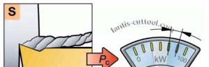 S-heat-resistant alloys and titanium alloys
• What is a heat-resistant alloy?
– heat-resistant alloys HRSA includes much high-alloy iron, nickel, cobalt, or titanium-based materials.
Group B: fe-base, ni-base, co-base
Working Conditions: Annealing, solution heat treatment, aging treatment, rolling, forging, casting.
Features:-higher alloy cobalt content than nickel ensures better heat resistance, higher tensile strength, and higher corrosion resistance.
• processing characteristics
– long chip material.
– difficulty in chip control. Serrated chip.
– Use a negative rake for ceramics and a positive rake for cemented carbides.
– cutting force per unit: Heat Resistant Alloy: 2400, something 3100 N / MM2.
Titanium Alloy: 1300-1400N / MM2.
– requires high cutting force and power.
– Milling with the Etna SM3523 / SM3531 brand.
 Class H-HARDENED steel
• What is hardened steel?
– hardened steel is the smallest grouping from a processing point of view.
– The unit contains quenched and tempered steel with a hardness of 45, something 65 HRC.
In general, the range of the hardness of the hard parts to be machined is between 55 and 68 HRC.
• processing characteristics:
– long chip material.
– relatively reasonable chip control.
– Negative Rake Angle required.
– Cutting force per unit: 2550-4870N / MM2.
– requires high cutting force and power.
3. The working condition and process of a material
Class P-STEEL
In this paper, we take Class P materials as an example; these requirements also apply to all other classes of materials, namely, Class M / K / N / S / h.
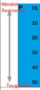
P01
Internal and external circular finishing turning; high cutting speed; small chip area; good surface quality; narrow tolerance; no vibration.
P10
Turning; profiling; thread processing; milling; high cutting speed; small to medium chip area.
P20
Turning; profiling; medium cutting speed; small chip area under turning end face; medium to painful working condition.
P30
Turning; End Milling; medium to low cutting speed; medium to large chip area; process including harsh working conditions.
P40
Turning; end face; milling; cutting; notch; low cutting speed; large chip area; as large a chip angle as possible; deplorable working conditions.
P50
Turning, turning, grooving, and cutting with tools of extremely high toughness; low cutting speed; large
Chip area; chip angles as wide as possible; extreme working conditions.
4. Knowledge of cutting edge related to blade
 Commonly used cutting edge form of milling insert.
• Negative Chamfer
The chamfering of a negative rake angle or zero or very small rake angle along the cutting edge, used chiefly in positive rake milling cutters
On, the role is to enhance the cutting edge, reduce tool collapse edge, improve tool life. Commonly used for steel parts and large
The processing allowance, Chamfer width, is generally (0.5 ~ 1 time per tooth feed, rake angle g01=5° ~-10°.
If milling with a hard surface of the workpiece impact, and the rigidity and power of the machine allows, you can
Use BR11 ~ 2 times feed per tooth, g01=10° ~-15°, or use double Chamfer.
The wear resistance of g01=15° ~-30° is better when milling hardened steel with ceramic insert.
 • Blade passivation
CUTTING EDGE BLUNT CIRCLE, the role is to enhance the cutting edge, improve the quality of cutting edge. The chamfered cutting edge has better impact resistance and longer life than chamfered cutting edge.
In light cutting, rn is about 0.03 mm, in medium cutting, rn is about 0.05 ~ 0.1 mm, in heavy cutting, rn is about 0.15 mm.
 • Chip Breaker
When processing soft materials, the rake angle increased, and when processing the materials with high toughness, the rake angle is also grown to break chips.
 • Chip Slot
Improve the cutting conditions, reduce milling force, improve milling efficiency. Generally, four blades, as a group, complete the cutting edge of the cutting graphics. Often with the use of scraping chip slot blade, suitable for large margin, blank processing.
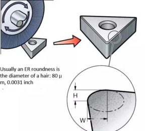 Er Treatment Brings micro-groove shape to cutting edge.
The 1.Er
Process (rounding of the cutting edge) is completed before the coating is applied and the final shape of the cutting edge (Microchannel.
2. The relationship between W and h depends on the application, and Lantis will customize passivation for the client based on the client’s operating conditions
Value. 02
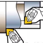
Negative chamfering increases the strength of the cutting edge
1. In some cases, the blade has a negative chamfer and a rounded corner that enhances the module so that it cuts at intervals
To become stronger and more reliable in reducing action.
2. Negative chamfering increases the strength of the cutting edge, but it also produces higher cutting force.
The passivated edge brings micro-groove to the cutting edge
1. Passivation cutting edge is also called ER processing, cutting edge strengthening, and so on.
2. The passivated advantage completed before the coat is applied, and the final shape of the cutting edge (micro-groove) is determined.
3. The passivated side can improve the strength of the border, prolong the tool life, and stabilize the cutting process.
4. The relationship between W / h depends on the application, and the customer service at LANTIS will set the passivation value for the customer according to the customer’s operating condition.
 Negative chamfering increases the strength of the cutting edge
1. In some cases, the blade has a negative chamfer and a rounded corner that enhances the module, making it stronger and more reliable in interrupted cutting.
2. Negative chamfering increases the strength of the cutting edge, but it also produces higher cutting force.
5. Troubleshooting instructions for Blade Edge
The troubleshooting steps shall be carried out in sequence to identify and eliminate problems in the milling process, which can be identified as early failure of the blade, workpiece appearance problems, machine tool noise or vibration, and tool appearance problems. Successful troubleshooting requires that we correctly identify the problem and then take the necessary corrective action, one step at a time. FIVE MAIN AREAS TO CONSIDER:
1. Blade material
2. Tool/joint
3. Machine tool
4. Workpiece
5. Setup / fixture
This article will discuss the recommended solutions in each of the five categories listed. Note that if you take multiple steps at once, you may never find the real reason. Always take one solution at a time, to better troubleshoot the problem.
Troubleshooting of cutting edge
Bludgeoned
In fact, the normal wear on the back of the blade has a very fine and smooth wear pattern, while on the chamfered edge formed by the collapse of the blade, there is a serrated and uneven surface, if the blade is not found in time, there will be deep cut damage.
A good example is that in slot milling applications, the chip holding space of the tool is not large enough to ensure the smooth removal of the chip, in this case, there will also be chip clogging. In most cases, the problem will be solved by replacing the blade with a more ductile material, or with a different edge treatment, such as a large chamfered or t-shaped Chamfer, or by replacing the 90(0) groove with the main offset groove, or a groove.
Deep Cut
It appears when the cutting edge collapses or local wear occurs at the cutting depth line of the front and back surface of the blade. The processing conditions of the workpiece materials mainly lead to the appearance of the notch, and the deep-cut damage caused by the processing conditions of the materials includes The scaly and Abrasive workpiece materials.
Hot Crack
The direction of travel of these cracks is perpendicular to the direction of the cutting edge of the blade, which is caused by a sharp change in temperature during milling, the change of chip thickness will also lead to the change of temperature during the cutting process. When the blade leaves the cutting part, the Compressed air or coolant will quickly cool the blade, the blade then re-enters the cutting area to begin cutting.
A sharp change in temperature can create thermal stress on the blade and lead to thermal cracks, which may be mistaken for cracks by non-professionals.
Chipping lump
Under this condition, the workpiece material will adhere to the upper surface of the blade, and the hardened adhesive material will fall off from time to time, forming irregular depression at the cutting edge. This will cause damage to the workpiece and the blade, because of the formation of debris, will also lead to increased cutting force.
Crescent depression wear
A relatively smooth, regular depression is formed on the blade’s rake face, and crescent depression wear occurs in two ways:
1. The workpiece material adhering to the upper surface of the blade will fall off and cause the small fragments of the upper surface of the blade to fall off together.
2. As the chips flow over the upper surface of the blade, the heat generated by friction builds up and accumulates, causing the chips to slough off and remove small chips from the blade until a crescent depression forms.
The wear of crescent depression is rare in milling, but it will happen when machining some steel parts and cast iron alloy. If the wear of crescent depression becomes serious, it may lead to the breakage of cutting edge and the invalidation of cutting blade.
Flank wear
Uniform flank wear is an ideal condition because it can help to predict the failure of the blade, and the excessive flank wear will lead to the increase of cutting force and result in poor surface accuracy, if the wear rate is too high or unpredictable, focus on the cutting speed, feed rate, material, and Blade/tool groove type.
Note: In Rough machining application, the blade should be rotated when the wear of the flank reaches 0.38-0.5 mm. In finishing the application, the blade should be rotated when the wear of the flank reaches 0.25-0.38 M.
Multiple Factors
If there are faults such as wear, breakage, hot crack, and breakage at the same time, the machine operator should find out the cause of the faults after normal adjustment of feed rate, cutting speed and cutting depth parameters, etc. , the cutting speed, feed rate, and depth of cut parameters should be double checked for accuracy, but the rigidity of the system should also be carefully checked for loose-fitting.
6. How To achieve good performance in various processes
 Turning
A durable cutting edge that can work for long periods of time is required, and continuous cutting at high temperatures is often required
• Good chip braking ability
- Good resistance to different types of wear and plastic deformation.
 Milling
- The cutting motion is always intermittent, and the cutting edge must have good overall strength to resist fracture
Interrupted cutting also results in a change in the cutting edge temperature, which also makes resistance to hot cracking very important
 Drilling
• The cutting edge must be strong enough to operate at very low cutting speeds over a sustained period of time, sometimes up to 0
• coolant is used primarily for chip transfer, but this places additional stress on the cutting edge due to changes in temperature
• Good chip breaking capability is important for conveying chips through narrow chip slots and holes
Anti-chip properties of different materials
Good chip formation usually results in high cutting forces and excessive heat, depending on the material. This, in turn, reduces the cutting speed and is accompanied by adhesive stress. On the other hand, aluminum, non-alloy steel, and low-strength cast iron and other materials produced less cutting force.


Leave A Comment