ONE-Deformation Of Metal Cutting Layer
The deformation of the metal cutting layer can represent by the slide line and streamline diagram in the metal cutting process. The flow line represents the path of the flow of a point in the cutting process of the metal cut and can divide into three deformations district:
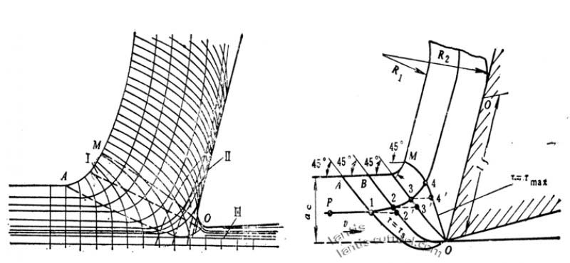
1. The first deformation zone: from the plastic deformation of OA line to the shear slip of Om Line Grains
Complete (SHEAR SLIP surface). This deformation determines the process of cutting, turning the cutting layer of the workpiece to cut into chips.
2. Second deformation zone: The chip is further squeezed and rubbed by the rake face when it discharged along the rake face. The metal underneath the chip near the rake face is fibrous and is substantially parallel to the rake face, and this area cut
The contact condition between chip and rake face has a significant influence on friction force and cutting force, and also determines Chip Coil
Qu, flow direction, break mode, therefore, is the core of the design of a three-dimensional groove.
3. The third deformation zone: The machined surface is squeezed and rubbed by the passivated round part of the cutting edge and the flank, resulting in deformation and rebound, resulting in fiber and processing hardening.
The three deformations concentrated near the cutting edge, where the stress is concentrated and complex
Tt is where the cutting layer separates from the material of the workpiece body, most of which become chips, and a small portion remains on the face of it.

- TYPE AND CONTROL OF CHIP
As the workpiece material is different, the degree of deformation in the cutting process is also different, so the types of chips produced are also diverse, as shown in the diagram. From left to right, the first three are chips for cutting plastic materials, and the last one chipped for cutting brittle materials.
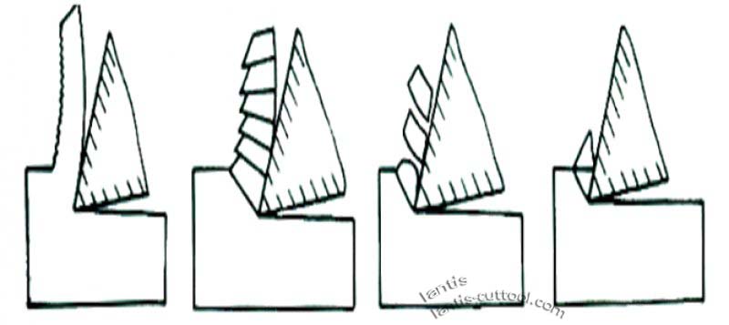
- FOUR TYPICAL FORMS OF CHIP
- ribbon chips
Its inner surface is smooth, and its outer surface is hairy. Processing of plastic metal materials, when the cutting thickness is small, cutting
When the cutting speed is high and the tool rake angle is large, such chips usually obtained. It’s cutting process is balanced, cutting
The cutting force fluctuation is small, and the processed Surface roughness is small.
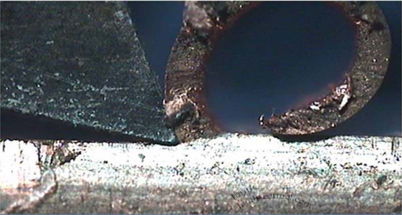
2.crush chips
These chips differ from the ribbon chips in that they are serrated on the outer surface and sometimes cracked on the inner surface. It’s.
Most kinds of chips produced when the cutting speed is low, the cutting thickness is large, and the tool rake angle is small.
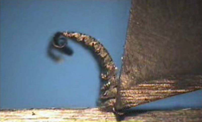
3.cell chips
If the crack extends over the whole surface on the shear plane of the squeeze chip, the entire element cut off TRAPEZOIDAL unit chip.
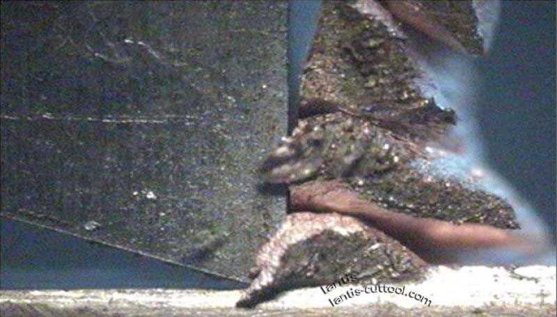
The above three kinds of chips can be obtained only in the processing of plastic materials. Among them, the cutting of ribbon chips
The process is the smoothest, and the unit chip’s cutting force fluctuates the most. In production, the most common is the band-shaped chip, there
When the fry crushed, the unit chip is very rare. If the conditions for squeezing the chip are changed, such as further reduction
Small Tool Rake Angle, reduce the cutting speed or increase the cutting thickness, you can get the unit chip. On the contrary, you get a band of chips. It shows that the chip shape can transformed with the cutting conditions. Got It
Its Change Law can control the chip deformation, shape, and size, to achieve the purpose of chip and chip breaking
4.crumble
These are chips of brittle materials. The shape of the chip is irregular, and the machined surface is convex and concave
Uneven. From the cutting process, the chip before the fracture deformation is tiny, and plastic material of the chip-forming machine
It’s a different theory. Its Brittle fracture is mainly due to the material subjected to stress exceeding its tensile limit. Hard and Brittle
Materials such as high silicon cast iron, White Iron, especially when the cutting thickness is large, often get this chip. By it’s cutting process is precarious, easy to damage the tool, but also damage the machine, the machined surface, and rough.
Therefore, the production should strive to avoid it. The method is to reduce the cutting thickness, to cause to chip into a needle or flake, Conduce to increase the cutting speed appropriately to increase the plasticity of the workpiece material.
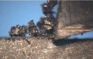
The above are four typical chips, but the chips obtained in the processing site are of various shapes.
In the modern cutting process, the cutting speed and metal removal rate has reached a very high level; cutting conditions are terrible poor quality, often producing large amounts of the unacceptable chip.
The so-called chip control is also known as chip processing, one of the plants
Generally referred to as chip-breaking refers to the cutting process to take appropriate measures to control the chip CRIMP, outflow, and broken so that the formation of a fine chipping acceptable chipping.
In the actual processing, the most widely used chip control method is in front of the tool surface, grinding out a chip-breaking groove or use the chip breaker.
TWO-The formation of chip accretion and its influence on the cutting process
At a given cutting speed, whether in the continuous or intermittent cutting of steel or cast iron,
a hard, sometimes triangular-shaped section often adheres to the rake face. It’s very hard. It’s usually industrial
Pieces of 2-3 times the material, in a relatively stable state, can replace the cutting edge.
This piece of metal cold welded to the front face of the knife is called a chipping lump or knife lump.
BUILD-UP OF DEBRIS:
1. The friction of the chip on the contact of the rake face makes the rake face very clean.
2. When the contact surface reaches a specific temperature, and the pressure is high at the same time, there will be a bonding phenomenon
The so-called Trompe l’oeil. The chips flow over the underside of the blade, forming internal friction.
3.If the temperature and pressure is appropriate, the metal above the bottom layer due to internal friction and deformation caused hard processing
And get stuck in the bottom layer and stick together.
4. The adhesive layer then grows until the temperature and pressure at the site are not sufficient to cause adhesion.
Therefore, the formation of the build-up of debris and its height is related to the hardening properties of metal materials, but also the edge
The temperature in the front zone is associated with the pressure distribution. Generally speaking, the stronger the working hardening tendency of plastic materials, the easier it is
If the temperature and pressure are too low, the accumulation of debris will not occur. If the temperature is too high, the mass of debris will weaken
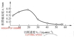
The action also won’t accumulate a SCURF tumor. The height of chip accretion is closely related to the cutting speed when the tool flow is kept constant
Relationships.
For Carbon Steel, the highest accumulation of debris is at about 300-350 °C and tends to disappear at 500 °C
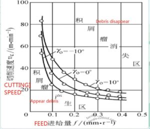
- Influence of chip accretion on the cutting process
1. Increase the actual Rake Angle
It increases the exact rake angle of the tool, reduces the cutting force, and plays an active role in the cutting process.
The higher the accumulated cuticle is, the larger the actual anterior angle is
2. Increase the cutting thickness, which may cause vibration;
3. Surface roughness
The bottom of the chipping tumor is relatively stable; its top is precarious, easy to break, a part attached
The chip discharged at the bottom of the chip, part of which remains on the machining surface, and the chip lump protrudes from the cutting edge part to form the machining table
Surface cutting is very rough, so in finishing must try to avoid or reduce the accumulation of debris tumor;
4. Impact on tool life
The chip accretion on the rake face can replace the cutting edge and reduce the tool grinding when the tool is relatively stable
The function of loss and improvement of life span. However, when using carbide cutting tools in the unstable situation of debris accumulation,
the breakage of the accumulated chip lump may make the hard alloy cutting tool particles exfoliate, but cause the wear aggravation.
- The main methods of inhibiting the formation of chipping tumor
1. Cutting speed is the influence of cutting temperature on the maximum friction coefficient of the rake face and the properties of working material
And the impact of chipping tumor, control cutting speed so that the cutting temperature under 300 °C or 500 °C above, It can reduce the formation of the SCURF tumor.
So either reduce the cutting speed, so that the temperature is lower adhesion phenomenon is not natural to occur Either high-speed cutting is used to make the cutting temperature higher than the corresponding temperature at which the chip lump disappears;
2. The bigger the feed, the bigger the cutting thickness, the longer the contact length of the tool and chip, and the chipping lump formed the basis for the creation. If the feed rate reduced correctly, the foundation of CHIPPING TUMOUR could BE WEAKENED
3. Use the cutting fluid with excellent lubricity to reduce the friction
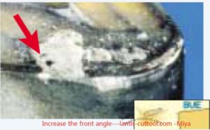
4.increase the tool rake angle, chip deformation reduced. Then the chip and The pressure in the contact area of the rake face is reduced, and the cutting force reduced the friction on the rake face cut, and the formation of the built-up debris lump reduced foundation.

It had proved that the chipping lump did not appear when the anterior angle increased to 35
5,.properly increase the hardness of workpiece materials, reduce the work hardening
Inclinations.

[…] 5. Troubleshooting instructions for Blade Edge […]
[…] The listed company processes turning, the machine tool condition is good, the processing quantity is […]