The origin of the milling cutter
A milling cutter is a cutting tool with a cylindrical shape and a cutting edge at the circumference and the bottom, which makes it rotate to cut the workpiece.
Milling cutters derived from planers. Because the plane has only one side of the blade, the plane in moving back and forth, only one side and cutting action, then the plane back time is completely wasted.
Moreover, the Planer blade is very narrow, so its processing efficiency is very low.
To overcome this shortcoming, people have to improve it.
The way is to Planer on a shaft, make it rotate quickly, let the workpiece slowly from below, this saves time, and this is the original milling cutter, also known as a single-edge milling cutter. After a long period of development, there are now a variety of milling cutters.
The classification of milling cutters
- according to the direction of the cutter teeth: divided into straight tooth milling cutter and spiral tooth milling cutter.
- according to the tooth back form: divided into sharp teeth milling cutter and shovel teeth milling cutter.
- according to the structure: divided into integral type, welding type, inlaid tooth type, indexable type.
- according to use: divided into cylindrical milling cutter, face milling cutter, disc milling cutter, saw Blade Milling Cutter, End Milling Cutter, keyway milling cutter, Mold Milling Cutter, Angle Milling Cutter, form milling cutter, etc.
Here’s a look at each of these four categories.
First, according to the direction of cutter teeth classification.
- Straight teeth, milling cutter teeth are straight, and milling cutter axis parallel. But now the ordinary milling cutter has very few consecutive teeth.
- Because all the tooth length of the milling cutter contact with the workpiece and leave the workpiece at the same time.
- The latter tooth has gone; the latter tooth may not have contact with the workpiece, it is easy to produce vibration, affects the processing accuracy, and reduces the life of the milling cutter.
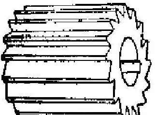
- Spiral tooth, this kind of milling cutter has a left-hand and right-hand difference, as shown in the figure.
- Because the cutter teeth are inclined around the cutter body, in the processing, the front teeth have not left, the back teeth have started cutting. In this way, there will be no vibration in the processing; the processing surface will be some light

Two, according to the tooth back form classification.
- Tooth Milling Cutter, this kind of milling cutter easy to manufacture, therefore the application is also very wide.
- After the teeth of the milling cutter are blunt in the tool grinder with grinding wheel teeth after the face, the front face in the production of the West is already done, do not need to grind.
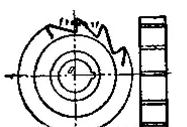
- Relieving Milling Cutter, this milling cutter is not flat flank, but a curve. The back face of the cutter made on a shoveling lathe.
- After the tooth relief milling cutter is blunt, it only needs to grind the front surface, but not the back cover.
- The characteristic of this kind of milling cutter is that it does not affect the shape of the cutter teeth when grinding the rake face
III. Classification by structure.
- INTEGRAL: the Cutter Body and the cutter teeth made into a whole.
- Manufacture is relatively simple, but large milling cutters generally do not make this kind of, because of the waste of materials.
- Welding type: the Cutter Teeth are made of hard alloy or other wear-resisting cutting tool material, and are brazed on the cutter body.
- INSET: This milling cutter made of the ordinary steel body and the tool steel insert blade to the knife body.
- Most large milling cutters use this method. Using the inlay method to manufacture milling cutter can save tool steel material; at the same time, if one of the cutter teeth is worn out, it can be removed to replace a good, do not have to sacrifice the whole milling cutter.
- However, because of the limited position of small-size milling cutters, it can not use inlaid teeth.

- Indexable type: A milling cutter that mechanically clips a polygonal blade capable of being indexable onto a cutter bar or body.
In cutting, when a point is blunt, the blade is rotated, and another location is used. The knife is dull and is not reground. Indexable milling cutters have the following advantages over other types of milling cutters:
- The defects of easy to produce crack during brazing of cemented carbide avoided.
- The indexable inserts are suitable for depositing thin layers of harder materials such as titanium carbide, titanium nitride, and aluminum oxide on the surface of cemented carbide inserts by vapor deposition to improve the cutting performance.
- Short Tool Change Time;
- Because the indexable inserts are standardized and centrally produced, the geometric parameters of the advertisements are easy to agree, and the chip control is stable.


Four.Classification by use.
- Cylindrical Milling Cutter
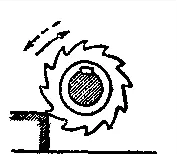
Cylindrical Milling Cutter is also called a plain milling cutter. This kind of milling cutter mounted on a slender cutter shaft, so it is necessary to pay special attention to the direction of rotation; the solid line is correct, the dotted line is wrong.
- End Mills
Shank type milling cutter with cutting Edge on peripheral surface and bottom.
Because the end milling cutter involves more, so we slowly understand, first we know the end milling cutter application and the name of various parts, here with a few pictures to let you know.
And then we’ll talk about the relationship between the number of blades and rigidity. The bigger the chip-containing groove, the smaller its rigidity, the lower the chip-containing slot, the higher its stiffness. In short, the lower the number of blades, the smaller the rigidity, the more the number of modules, and the higher the rigidity.

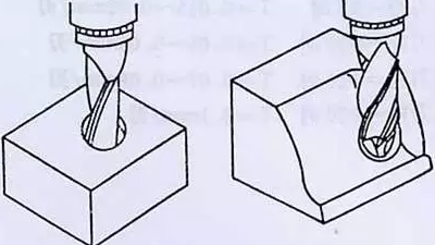

- End Mills
The end milling cutter is a kind of cutting tool which uses the cutter teeth on the top of the cutter to perform cutting work.
If the diameter of the milling cutter is smaller than the machining surface of the workpiece, the cutter teeth on the circumference of the milling cutter can also perform the cutting work by milling the surface of a workpiece several times.
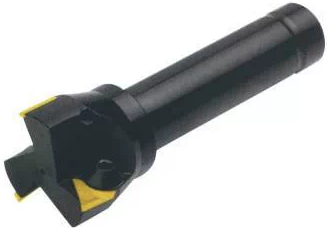
4.Face Milling Cutter
The leading Cutting Edge of the face milling cutter distributed on the surface of the cylinder or cone, the end cutting Edge is the leading cutting edge, and the side cutting edge distributed on the end face and mainly used for processing step surface and plane, high production efficiency.
Click this link to know more about the wear of the inserts:https://lantis-cuttool.com/wear-and-tear-of-cutting-tools/
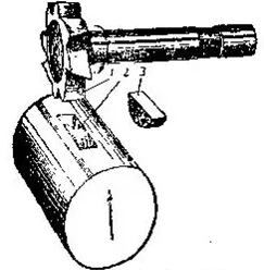
- Keyway milling cutter
Keyway milling cutter generally only two-blade, cylindrical surface and end face have cutting Edge. When processing, the first axial feed to reach the groove depth, and then along the keyway direction milling out keyway length.
They mainly used for processing round head closed keyway. But there are many kinds of keyways, such as a keyway is the rounded bottom, the key is semicircular, called a curved key.
Then the milling cutter for this keyway is drawn around keyway milling cutter
- Disk Milling Cutter
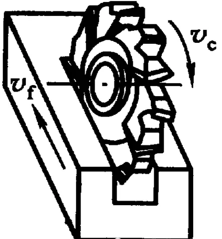
DISC MILLING CUTTER: double-sided Edge, processing step surface; three-sided Edge (can be divided into straight teeth, staggered teeth and inlaid teeth), processing slot; Slot Milling Cutter, processing groove, Horizontal Milling Machine.
- t-slot milling cutter
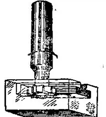
Generally, there is an at-slot machine; this t-slot milling method is first milling a straight slot and then use an at-slot milling cutter to milling out the bottom of the flat slot, as shown in the figure.

- Dovetail Slot Milling Cutter
Dovetail Slot Milling Cutter is used to milling a dovetail slot.
- Side Milling Cutter
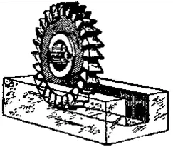
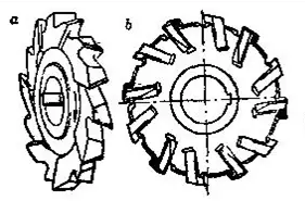
The side milling cutter mainly used for milling Groove, so milling cutter on the three sides has a blade; that is, both parties and circumference have an edge. Side milling cutters are also divided into two; one is the circumference of the teeth of the blade and axis-parallel, as shown in figure 1;
the other teeth of the module are staggered, as shown in figure 2.
The second one has a more massive chip clearance than the first one and is easier to cut, so a higher cutting speed and feed can be used.
But this kind of milling cutter has a big flaw: after the milling cutter is blunt, the three sides of the blade must be reground, can be used again.
So there are two sides of the knife blade than the original narrow, and then milling out of the groove is smaller than before.
If you want to keep the slot width the same, you can use two side milling cutter together, as shown in the figure, the gasket can replace the middle of the two milling cutter, so you can adjust the thickness of the gasket to fit the milling cutter width and narrow.
- Mould Milling Cutter
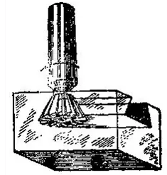
Die Milling Cutter is evolved from end milling cutter, mainly used for machining die cavity or punch forming surface. According to the working part, a shape can be divided into three cone-shaped flat heads, cylindrical, spherical head, cone-shaped spherical head.
Carbide Mould Milling Cutter is widely used.
It can be used to clean the burrs of casting, forging and welding parts, and finish some forming surfaces.
The utility model can be mounted on pneumatic or an electric tool, and tens of times increase the production efficiency and durability of the milling cutter compared with grinding wheels and files.
- Angle cutters
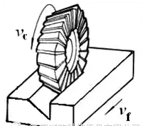
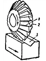
Angle Milling Cutter: For Milling into a certain angle of the groove, there are single-angle and double-angle milling cutters.
- Thread cutters
Thread Milling Cutter, as the name suggests, is used to process the thread of the milling cutter.
- Form Milling Cutter
The forming cutter is used to process the forming surface. The profile of the cutter teeth is determined according to the profile of the workpiece to be processed.


How to chose the Milling cutter and the milling cutter process
Milling’s development has made it possible for manufacturers to save a lot of time and cost by improving Milling’s efficiency.
Thus, by selecting the right milling cutter for the machining task, by using the rolling cut method in the face milling processing, and by using the milling cutter to process the holes when the conditions are suitable, the manufacturer May, without the need to invest in new equipment, a substantial increase in production capacity.
When choosing the milling cutter, which is suitable for the machining task, the geometric shape, dimension, and material of the workpiece must be considered.
The central deflection angle of milling cutter
- The central deflection angle is the angle between the cutting edge and the cutting plane. The central deflection angle has a significant influence on the radial cutting force and cutting depth.
- The radial cutting force directly affects the cutting power and the anti-vibration performance of the cutting tool. The smaller the central deflection angle of the milling cutter, the lower the radial cutting force and the better the vibration resistance, but the cutting depth also decreases.
- The central deflection angle of 90 is selected when milling the plane with a square shoulder. The utility model has the advantages of good generality and can use in a single piece and small-batch processing.
- Because the radial cutting force is equal to the cutting force, feed resistance is significant.
- The vibration is natural, so the machine tool is required to have high power and enough rigidity. When machining the plane with a square shoulder, the milling cutter with 88 central deflection angle can also be selected. Compared with the milling cutter with a 90 central deflection angle, its cutting performance is somewhat improved.
- A 90 square shoulder milling cutter for surface milling is also very common.
- In some cases, the choice has merit. Milling of irregular workpiece shape or casting surface will lead to changes in depth of cut, square shoulder milling cutter may be the best choice. In other cases, however, it may be more beneficial to use a standard 45 face cutter.
The dimension of Milling Cutter
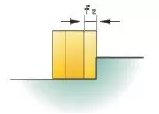
- The diameter of the standard indexable face milling cutter is 16 ~ 630mm. The diameter of the milling cutter should be selected according to milling width and depth. The larger the depth and breadth before Milling, the larger the diameter of the milling cutter.
- When rough Milling, the milling cutter diameter should be smaller; when fine Milling, the milling cutter diameter should be more significant, to contain the whole processing width of the workpiece and reduce the tool mark between two adjacent feed.
- In the face milling of large parts, the use of a small diameter of the milling cutter leaves much room for productivity. Ideally, the milling cutter should have 70% of the cutting edge to cut.
- When milling a hole with a milling cutter, the size of the cutter becomes particularly important.
- If the cutter diameter is too small relative to the hole diameter, a core may be formed in the center of the hole during machining.
- When the base falls, it may damage the workpiece or the tool. Excessive milling cutter diameter will destroy the machine itself and workpiece, because the milling cutter is not in the center of cutting, maybe in the bottom of the tool collision.
Milling Mode
- Another way to improve Milling is to optimize the milling strategy of the face milling cutter. When programming for plane milling, the user must first consider how the cutter cuts into the workpiece.
- Usually, the milling cutter cuts directly into the workpiece figure 1. A significant impact noise generally accompanies this cutting because the milling cutter produces the thickest chip when the blade removed from the cutting.
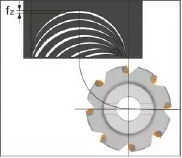
- Because the module has a significant impact on the workpiece material, it often causes vibration and creates tensile stress, which can shorten the tool life.
- A better approach is to adopt a rolling cutting method, that is, without reducing the feed rate and cutting speed, milling Cutter Rolling Cutting workpiece figure 2.
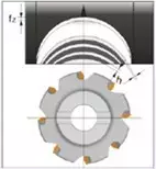
- This means that the milling cutter must be rotated clockwise to ensure that it is machined in a milling fashion. The chips thus formed are thick to thin, reducing vibration and the tensile stress acting on the tool, and transferring more cutting heat into the chips.
- By changing the way the milling cutter cuts into the workpiece, the service life of the cutter can be extended 1-2 times. To realize this feed mode, the tool path’s programming radius should be 1 / 2 of the cutter diameter, and the offset distance from the tool to the workpiece should be increased.
- Although the rolling cutting method is mainly used to improve the way the cutter cuts into the workpiece, the same principle can be applied to other stages of Milling.
- For Large area surface milling, the standard programming method is to let the cutter go along the full length of the workpiece and finish the next cutting in the opposite direction.
- The combination of screw-down Cutter and Rolling Milling workpiece angle is usually more effective to keep constant radial feed and eliminate vibration.
- Rotary Milling of the workpiece angle can eliminate noise and extend tool life. Generally speaking, the turning radius of the workpiece should be 75%-100% of the milling cutter diameter, which can reduce the cutter arc length and vibration, and allow a higher feed rate.
- To extend the tool life, in the face milling process, we should try to avoid cutting tools from the hole on the workpiece or interrupted parts through when the face milling cutter passes through the middle of a hole on the workpiece, the cutter milling along one side of the hole and against the other side of the breach, which will cause a significant impact on the blade. This can be avoided by bypassing holes and cavities when programming the tool path.
- By selecting the Proper Milling Angle, dimension and feed mode, the cutter can cut into the workpiece material in a way that minimizes vibration and tensile stress, and know in which case the milling hole is more effective than drilling, manufacturers can be efficient, low-cost workpiece blank processing into delicate parts.
How to choose the milling cutter under complex process conditions
To improve the machining quality and repeat precision to the maximum, it is necessary to select and determine the right cutting tools.
The selection of cutting tools is especially crucial for some challenging and difficult machining.
1.High-speed tool path
The CAD / Cam System can achieve high cutting accuracy by precisely controlling the arc length of the feeding tool in the high-speed cycloidal tool path. When the milling cutter cut into the corner or cut into other complex geometry, eat the amount of cutter will not increase.
To take full advantage of this technological advance, tool manufacturers have designed and developed advanced small-diameter milling cutters. Using a high-speed tool path, the small-diameter milling cutter can cut more workpiece materials per unit time and obtain a higher metal removal rate.
In machining, too much contact between cutter and workpiece surface is easy to lead to tool failure.
A useful rule of thumb is to use a milling cutter whose diameter is about 1 / 2 of the narrowest part of the workpiece.
When the radius of the milling cutter is less than the narrowest part of the workpiece size, the cutter will have space to move around and can get the smallest knife-eating angle. Milling cutters can use more cutting edges and higher feed rates.
Besides, the diameter of the workpiece for the narrowest part of the size of 1 / 2 of the Milling Cutter, you can maintain a smaller angle to eat the cutter, and in the tool will not increase when turning.
The stiffness of the machine tool also helps to determine the size of the device to be used. For example, when cutting on a 40-taper machine tool, the milling cutter diameter should generally be less than 12.7 mm. Using a larger diameter milling cutter, on the other hand, can generate larger cutting forces than the machine can handle, resulting in chatter, deformation, Surface finish, and shorter tool life.
With newer high-speed tool paths, the milling cutter produces the same sound at the corners as it does when cutting straight. The milling cutter provides the same music throughout the cutting process, indicating that it has not subjected to significant thermal and mechanical impacts. The squeal of the milling cutter, each time it turns or cuts the corner, suggests that the cutter diameter may need to reduced to reduce the cutter’s angle. The sound of cutting remains constant, indicating that the cutting pressure is uniform and does not fluctuate with the geometry of the workpiece since the edge at which the cutter fed remains constant.




2.Milling of small parts
The large feed milling cutter is suitable for the milling of small parts, which can produce the effect of chip thinning and make it milling with a higher feed rate.
In the processing of spiral milling hole and milling rib plate, the cutter will inevitably have more contact with the processed surface, and the use of large feed milling cutter can minimize the connection with the surface of the workpiece, thus reducing cutting heat and tool deformation.
In these two kinds of processing, the big feed milling cutter is usually in the semi-closed state. Therefore, the maximum radial cutter step should be 25% of the diameter of the milling cutter, and the maximum z-direction cutting depth of each cutter should be 2% of the width of the milling cutter.
In the spiral milling hole, when the milling cutter cuts into the workpiece with the spiral cutter path, the spiral cutting angle is 2 ~ 3, until the Z direction cutting depth of the milling cutter diameter is 2%.
If the large feed milling cutter is in an open cutting state, its radial tool step depends on the hardness of the workpiece material.
When milling the workpiece with HRC30-50 hardness, the maximum radial level should be 5% of the diameter of the milling cutter; when the material hardness is higher than HRC50, the maximum radial step and the maximum z cutting depth of each level are 2% of the diameter of the milling cutter.
3.Milling Straight Wall
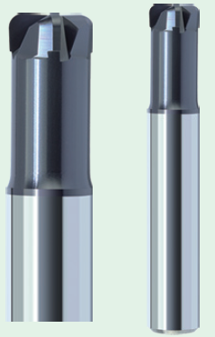
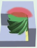
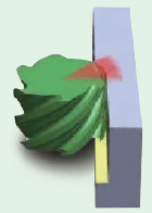
In the milling process with a flat rib plate or straight wall, the use of arc milling cutter the best effect. The 4-6 edge arc milling cutter is especially suitable for profile milling of parts with consecutive walls or very open.
The more the number of milling Cutter Blade, the higher the feed rate can be adopted.
However, the machining programmer still needs to minimize the surface contact between the tool and the workpiece and use a smaller radial cut width.
When machining on the machine with poor rigidity, it is advantageous to use the milling cutter with a smaller diameter, which can reduce contact with the surface of the workpiece.
The step distance and a cutting depth of the multi-edge arc milling cutter are the same as those of the large feed milling cutter. The cycloidal tool path can be used for grooving of hardened materials.
Ensure that the cutter diameter is about 50% of the groove width, enough space for the cutter to move and that the feed angle does not increase and generate too much heat.
The best tool for a particular process depends not only on the material to cut but also on the cutting and milling methods used. By optimizing tools, cutting speeds, feed rates, and machining programming skills, parts can be produced faster and better with lower processing costs.



Leave A Comment