Craft / process
Craft
- According to the diameter and total length of the drill bit, alloy bar cutting machine or wire cutting machine can be selected.
- The cutting bar with fixed length can carry out on a hand tool grinder.
- Chamfering or drilling the finished end face of the alloy bar to prepare for grinding the drill’s outer diameter and Shank, depending on whether the external cylindrical grinding fixture is a positive or negative top.

- To ensure the cylindricity of the outside diameter of the drill bit, the outer diameter of the drill bit and the outside diameter of the Shank are machined on the high precision cylindrical grinder. The design requirements of the outside diameter circular degree, the round runout, the Surface finish, etc.
- To improve the machining efficiency of the CNC grinder, chamfering the drill point on the alloy rod before the CNC grinder, such as 140° drill point angle when chamfering it can be roughed to 142°.
- After the chamfered alloy bar cleaned, it is transferred to the CNC grinder to process all parts of the drill bit.

- If you need to improve the surface finish of the drill, you can also use the wool wheel and abrasive to polish the drill before or after the 5th step. Of course, the drill needs more work.
- For the processed qualified bit, laser marking, content, or for the company LOGO and bit size information.
- Package the marked bit and ship to a professional tool coating company for coating.
Note
- If the bit is slotted, or spiral or straight slotted, this step also includes negative chamfering of the circumferential edge; then the drill point edge is processed, including the gap part of the drill point and the back corner part of the drill point; and then the back part of the drill edge is processed, grinding out a certain amount of drop to ensure that the outer diameter of the drill edge and the workpiece hole-wall contact surface in a specific proportion control.
- The machining of negative chamfering of drill point edge can be divided into a CNC grinding machine or manual machining, which is different from each factory.
Processing problem
- It is necessary to pay attention to the failure of the Jig when grinding the drill bit and to keep the good habit of measuring the outer diameter of the drill point by thoroughly cooling the Alloy Rod.
- When the bit machined on the CNC grinder, the two steps of roughing and finishing are separated as far as possible to avoid the potential hot crack caused by too much grinding, which affects the service life of the tool.
- A well-designed material plate is used for tool handling to avoid cutting edge damage caused by tool collision.
- To grind the blackened diamond wheel, the oil stone used for cutting edge treatment in time.
Note:
According to the materials/equipment/working conditions, the processes are different. The above process arrangement only represents the author’s personal opinion, only as a technical exchange.
The material of Drill Bits
High-speed steel
- High-Speed Steel (HSS) is a tool steel with high hardness, high wear resistance, and high heat resistance, also known as high-speed tool steel or sharp steel, commonly known as White Steel.
- A high-speed steel tool is a kind of device which is more robust and more comfortable to cut than a standard tool. High-speed steel has better toughness, strength, and heat resistance than carbon tool steel.
- The cutting speed is much higher than carbon tool steel (iron-carbon alloy), therefore named high-speed steel, cemented carbide steel is better than high-speed steel, cutting speed can be increased 2-3 times.
Characteristics
The hardness of high-speed steel can reach 650 degrees.
High-speed steel has good strength and toughness, sharp cutting edge, and stable quality.

Cemented Carbide
- Cemented Carbide, bit material for the main composition of Tungsten Carbide and cobalt, accounts for 99% of all components, 1% for other metals, and so is called Tungsten Steel (cemented carbide).
- Tungsten steel is a sintered composite consisting of at least one metal carbide.
- Tungsten carbide, cobalt carbide, Niobium Carbide, titanium carbide, Tantalum Carbide are the standard components of tungsten steel. The grain size of the carbide component or phase is usually between 0.2 and 10 microns, and the carbide grains bonded together using a metal binder. Bond metal is generally iron group metal, commonly used is cobalt, nickel.
- So we have tungsten cobalt alloy, tungsten nickel alloy, and tungsten titanium cobalt alloy.
- The sintering process of tungsten steel bit is to press the powder into blank, then heat it to a specific temperature (sintering temperature) in a sintering furnace, keep it for a certain time (holding time), then cool it down to get the required properties of tungsten steel.
Characteristics
- Hard alloy red hardness can reach 800-1000 degrees.
- The cutting speed of hard alloy is 4-7 times higher than that of high-speed steel. High cutting efficiency.
- Disadvantages are low bending strength, poor impact toughness, Brittleness, little impact, and anti-vibration capacity.
Application Problems/measures
Drill point wear
Reason:
- The workpiece will move down under the action of the Bit Entry Force.
- The rigidity of the machine tool is not enough.
- The bit material is not strong enough.
- The drill bit is beating too much.
- The clamping rigidity is not enough; the bit slides.
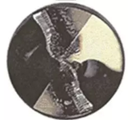
Measures:
- Reduce cutting speed.
- Increase your feed.
- Adjust Cooling Direction (internal cooling).
- Add A chamfer.
- Check and adjust the coaxiality of the drill bit.
- Check the rear corner.

Ligamentous collapse
Reason:
- The workpiece will move down under the action of the Bit Entry Force.
- The rigidity of the machine tool is not enough.
- The bits’ material is not strong enough.
- The drill bit is beating too much.
- The clamping rigidity is not enough; the bit slides.
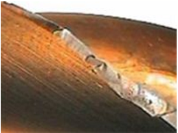
Measures:
- Choose a bit with a giant back cone.
- Check the jumping range of spindle bit (< 0.02 mm)
- Drill the top hole with a pre-set center.
- Use a more rigid bit, a hydraulic chuck with a necked or heat-shrinkable sleeve.
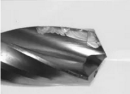
Burr cutting
Reason:
- It is caused by a chemical reaction between the cutting and the workpiece material (low carbon steel with high carbon content).
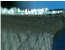
Measures:
- Improve the lubricant, increase the oil or additive content.
- Increase cutting speed, reduce feed rate, and reduce contact time.
- If drilling aluminum, the surface can be polished without a coating of the drill.

Broken knife
Reason:
- The spiral flute of the drill bit blocked by cutting, and the cutting not discharged in time.
- When the hole drilled quickly, there is no reduction of feed or manual feed.
- When drilling soft metals such as brass, the drill angle is too large, and the rake angle is not polished.
- The drill edge is too sharp, resulting in the phenomenon of cutting edge, and not quickly retreat.
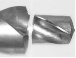
Measures:
- Shorten the tool replacement cycle.
- Improve the installation of fixed, such as increasing the support area, increase the clamping force.
- Check spindle bearings and sliding slots.
- Use precision tool handles, such as hydraulic tool handles.
- Use stronger materials.

Professional Name
- Spiral Angle: different models angle different, generally 10-40.
- Edge band: mainly for guiding and extruding.
- KNIFE BACK: the part between the edge band and the GROOVE, but lower than the edge band, reducing and cutting force (friction).
- The surface of a chip discharge groove: sometimes the face of a knife, through which chips flow.
- DRILL POINT: The point at which the edge band meets the cutting edge.


- Leading cutting edge: The angle between the two leading cutting edges is the VERTEX angle.
- FLANK: The face that forms the back corner.
- BLADE: It joins two cutting wedges and bears 50% of the cutting force (axial).
- Rear Clearance: Reduces friction between bit and workpiece.
- Chip Removal Slot: Larger space, conducive to chip removal.


Bit’s Angle
α:Rear Horn.
φ:Edge Angle.
Apex Angle.
β:Wedge Angle.
γ:Anterior Horn.

Chip formation at each point
① 6mm ② 3.5mm ③ 1.25mm
④ 0.75mm⑤ 0.5mm⑥ 0.25mm


Cold bore
- Coolant can increase line speed.
- Coolant can help remove debris.
- The cooling liquid has the lubrication function, prevents the accumulation of truncates the lump to produce.


Shape and characteristics of the transverse blade
- The higher the cutting speed is, the lower the cutting speed is with the approach to the center, and the cutting speed is zero at the center of the rotary center of the edge of the bit.
- Therefore, in the drilling process, 50%-70% of the axial force is consumed in the bit’s transverse edge.
- To reduce the cutting power and the part of the sloping side, the core thickness of the bit must be reduced.
- Still, the core thickness is too small, the strength of the bit will be diminished, and the deflection will cause the vibration, or the service life of the bit will be shortened, and the fracture phenomenon will occur, so there’s a limit to reducing core thickness.
- Combining the shape of the cutting edge of the drill point and the grinding of the cutting edge can further reduce the cutting force and improve the hole accuracy.

Leave A Comment