To remove excess (or reserved) metal from work through a metal cutting tool, thereby obtaining a shape, dimensional accuracy and surface quality are following the predetermined requirements of the processing, called metal cutting.
In the process of cutting, there must be relative cutting. The metal cutting machine makes Movement between the tool and the workpiece, which is caused by the Machine tools, fixtures, tools, and workpieces, which constitute the metal cutting process system, cutting process.
All kinds of phenomena, laws, and their essence should be investigated and studied in the motion state of the processing system.
One -Movement and machined surfaces in turning
Turning is a common and typical cutting method. As shown in FIG. , normal cylindrical turning plus
The cutting motion in the industry is composed of two kinds of motion units, one of which is the rotary motion of the workpiece, which is cutting
In addition to the surplus metal to form the surface of the basic Movement, the other is the lathe tool (vertical or horizontal) to the change. It ensures that the cutting work carried out continuously.
Under the action of the cutting motion, the cutting layer on the workpiece is continuously cut by the turning tool and transformed into chips, thus adding the mill produces the new surface of the workpiece. During the formation of this surface, there is three constantly changing surface:
- Surface to be machined: the surface on which the metal layer is to cut;
- Machined surface: the surface on which the cutting edge is cutting;
- Finished surface: A new surface formed by the removal of excess metal.
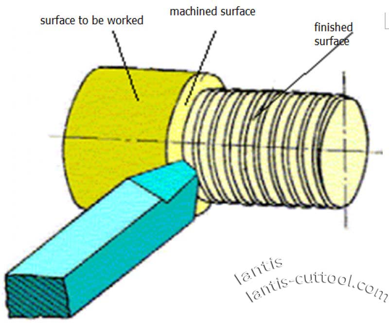
These definitions also apply to other forms of metal cutting.
Two-Cutting motion unit and its combination concept
The cutting motion of all kinds of cutting processing is composed of some simple moving units. Straight line
Motion and Rotary motion are two basic motion units in reducing. For the different number of moving units, press.
According to different size ratio, different relative position, and direction combination, that is, constitute a variety of cutting
Sports. For example:
A straight line movement, planing, broaching. A Rotary Movement, disc broach processing;
A combination of rotary motion and linear motion for turning, boring, milling, drilling, reaming and turning screws
Grain, tapping, it is currently the most widely used in a combination of forms; Two straight-line motion combination saw, profiling planing;
Two Rotary motion combination, milling Rotary Body surface (interpolation) ;
Two Rotary motion and a linear motion combination, milling spiral groove, milling thread, grinding external circle, grinding internal ring,
HOB hob gear, it is also a widely used form of a movement combination.
Three-Three elements: Main Motion, feed motion, and cutting parameters
The moving units of the machining, as mentioned earlier, methods.
There are two kinds of motion: The main action and the feed motion in the cutting process,
- Main exercise
The cutting layer on the workpiece is directly removed and converted into chips to form the Movement of the new surface of the workpiece
The first motion is represented by the cutting speed (VC). Usually, the main action is higher in rate and consumes the cutting
And it’s got a lot of power. For example, the turning motion of the workpiece during turning, the turning motion of the milling cutter during milling, and
The straight-line Movement of Broach in broaching. It’s all about the sport.
The central velocity, the cutting speed, is calculated as follows: Vc=p*d*n/1000
In formula:
d — workpiece diameter dw or tool (grinding wheel) diameter do (mm):
n– speed (r / min) of workpiece or cutter (grinding wheel).
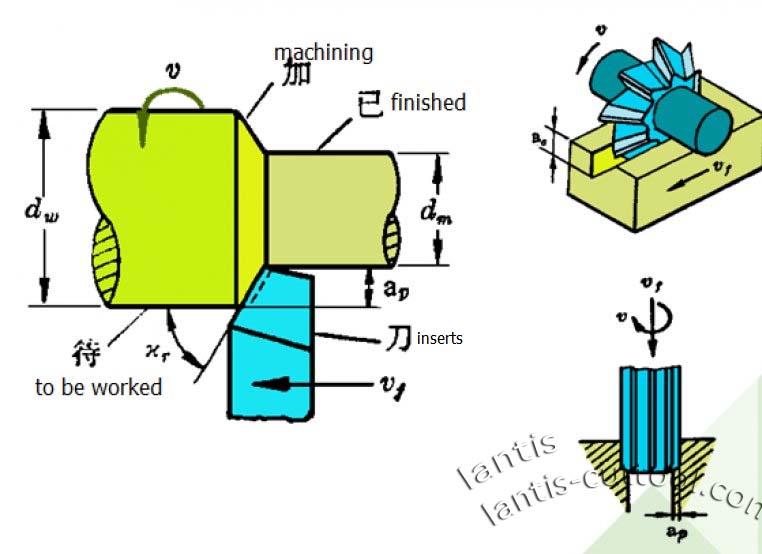
For rotating parts or rotating tools, in a fixed speed, because of the cutting edge of the point of rotation
The cutting rate varies with the radius. In the calculation, the maximum cutting speed shall prevail. Like the outer circle
The rate on the surface to be machined calculated during turning, and the speed at the outer diameter of the bit is calculated during drilling. This is because of the
The cutting tool aspect considers the place which the rate is significant, gives off heat much, the attrition is quick, should give the attention.
- Feed motion
The cutting layer is continuously put into the cutting motion, which is called feed motion, using feed speed Vf mm / Min
Or Feed Rate f, fz to express.
The vertical and horizontal movements of the turning tool, the axial changes of the drill bit and Reamer, and milling are shown in the figure on the previous page.
When the workpiece vertical, lateral Movement. Are feeding Movement. The unit of Feed f is mm / r, the workpiece Or the relative displacement of the two tools in the direction of feed for each rotation; if the main motion is a reciprocating linear motion.
Feed f measured in mm/str (mm / double stroke). fz Is a multi-edge cutting tool Feed per tooth (e. g. milling, reaming, pulling) in mm / Z.
Vf=f*n= Fz *Z* n (mm / min).
Usually, there is only one main motion in cutting, and the feed motion may be one or more.
- Depth of cut
The cutting depth ap is the vertical distance between the machined surface and the surface to be machined on the workpiece. In mm;
The size of the ap directly affects the working length of the leading cutting edge and reflects the size of the cutting load.
For cylindrical turning,
ap= dw-dm / 2 (mm )
For drilling work
ap=dm/2(mm)
FORMULA: Diameter of machined surface dm; dw — working surface diameter mm.
- The combination of the main motion and the feed motion
The main motion and feed motion can be accomplished by the cutter or workpiece separately or by the cutter alone
For technical reasons, it is not convenient for the workpiece to be finished apart.
The main Movement and feed movement can be carried out simultaneously (such as turning, milling), or (such as planing) Pare, slop, Pare). At some point on the cutting edge of the tool while it is processed.
The motion relative to the workpiece is called the cutting motion, using the resultant velocity
Vector ve to represent;
Take cylindrical turning as an example; the synthetic velocity vector ve is equal to the main transport: The vector sum of dynamic velocity Vc and feed velocity vf.

Four-Cutting layer parameters
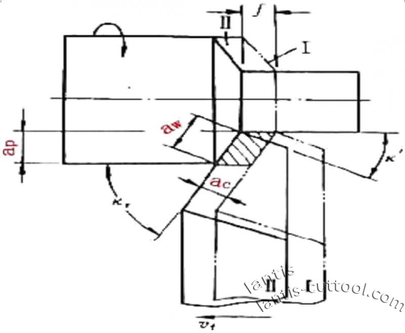
- CUTTING THICKNESS ac:
The dimension of the cutting layer measured in a direction perpendicular to the cutting edge.
If the leading cutting edge of the turning tool is a straight line and the angle of the cutting edge is λs =0°, then the size of the ac=f·sin kr can represent the size of the working load on the cutting edge per unit length.
If the cutting edge is an ARC or an arbitrary curve, the corresponding points on the cutting edge of the cutting thickness is not equal.
2.CUTTING WIDTH aw:
The dimension of the cutting layer measured in a direction perpendicular to the cutting edge.
If the leading cutting edge of the turning tool is a straight line and the angle of the cutting edge is
λs = 0°,aw=ap/sin kr ; and
λs = 0°,and kr=90°,
then ac = f ,aw = ap
3. CUTTING AREA ac:
is the area of the cutting layer in the base.
Ac = f ·ap.
Five-Basic terminology of cutting tools
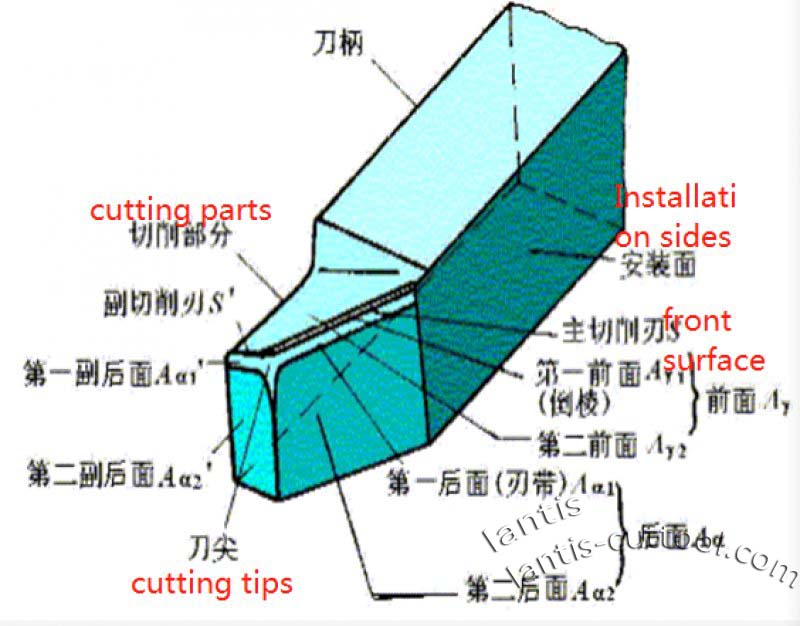
FRONT SYNONYM: Front face — the surface on which chips flow. It acts directly on the metal cutting. The generic layer and controls the blade along which the chips are discharging.
SYNONYMS: FLANK — the surface that is opposite to the surface produced by cutting on the workpiece.
Main back synonym: main back face — the back of the leading cutting edge formed by the intersection of the tool and the front. It’s the right to transition surface.
PARATAXIS SYNONYM: PARATAXIS — The flank of a tool that intersects the front to form the back of the parataxis cutting edge. It’s right Machined surface.
Main cutting edge-starts at the point on the cutting edge where the primary offset angle is zero and has at least one cutting edge used in the work. The entire section of the cutting edge on which the transition surface cut.
AUXILIARY CUTTING EDGE — the edge on the cutting edge other than the leading cutting edge, also begins at the point on the cutting edge where the maximum offset angle is zero. But it extends away from the leading cutting edge.
Tool angle reference system
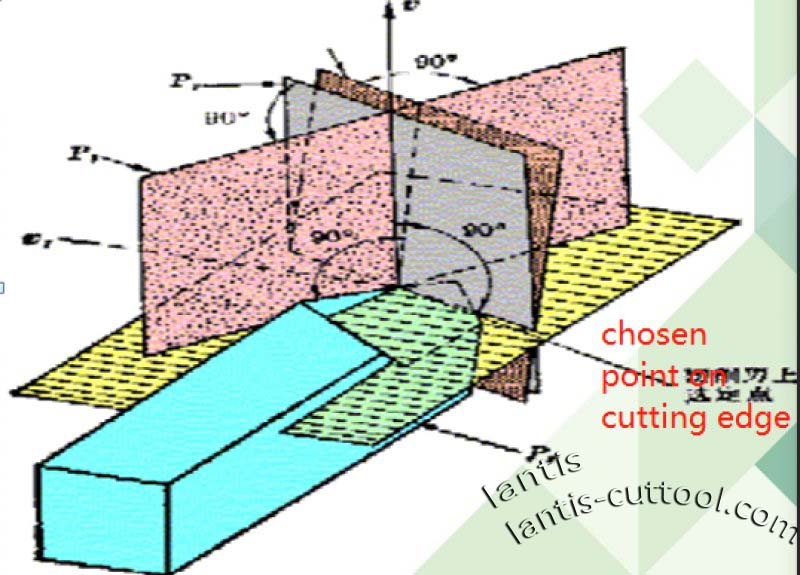
Cutting plane-a plane in which the cutting edge cut at a point selected by the cutting edge and perpendicular to the base surface.
The central cutting plane Ps in which the leading cutting edge is cut at a selected point on the cutting edge perpendicular to the base surface. It cuts at the transition surface, that is, it is a plane composed of cutting speed and cutting edge cutting line.
SUB-CUTTING PLANE-A plane in which a selected point on the cutting edge cut with the sub-cutting edge perpendicular to the base surface.
A plane with a cutting edge on which the selected point is perpendicular to the direction of the synthetic cutting speed. A tool rest In the reference frame, it is the plane through which the chosen aspects of the cutting edge are parallel or perpendicular to the tool during manufacture, grinding and measurement.
A flight or axis that is suitable for mounting or positioning, generally perpendicular to the assumed principal direction
The direction of motion.
Assume the working plane-in the tool Rest frame, and it is over the selected point of the cutting edge and perpendicular to the base surface
A plane or shaft parallel to or perpendicular to a tool that is suitable for mounting or positioning during manufacture, sharpening, and measurement
A line, in general, is oriented parallel to the assumed direction of principal motion.
Normal plane on-the plane in which the cutting edge is perpendicular to the cutting edge at a selected point.
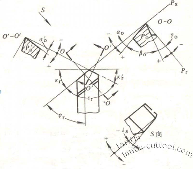
Rake Angle — The angle between the front and the base.
Back Angle — The angle between the back and the cutting plane.
Wedge Angle — The angle between the front and back.
The primary deflection-the angle between the central cutting plane and the assumed working plane, measured in the base plane.
The sub-declination-the angle between the sub-cutting plane and the assumed working plane, measured in the base plane.
Tool Point angle-the angle between the central cutting plane and the sub-cutting plane, measured in the base plane.
Edge dip-the angle between the leading cutting edge and the base surface, measured in the central cutting plane.
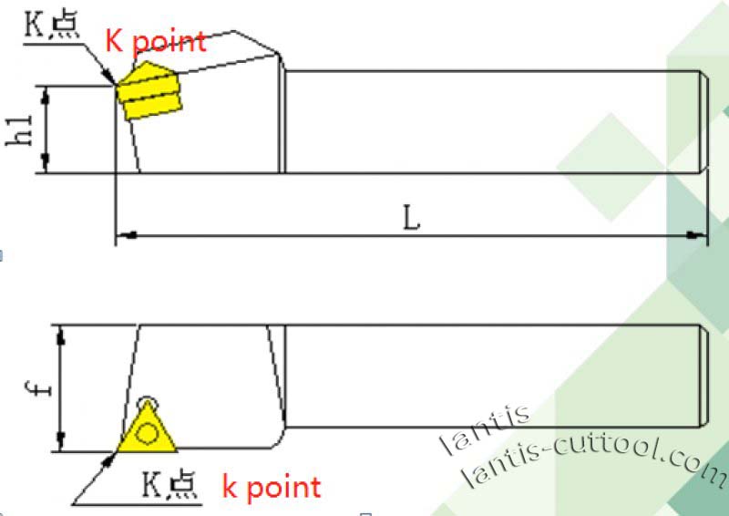
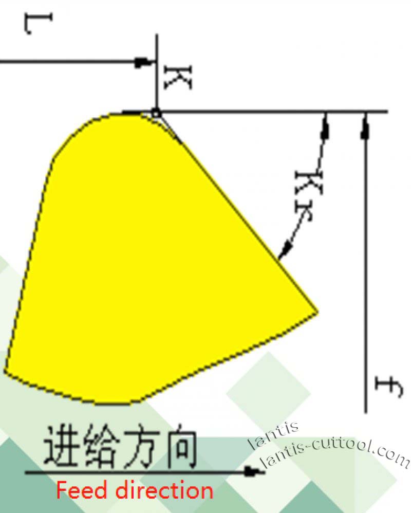
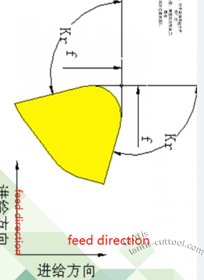
Determination of Reference Point for dimension measurement of indexable turning tools
It is suitable for all kinds of indexable turning tools, and it needs to calculate and measure the length and dimension of the turning tool, which the height of the tooltip or the size from the tooltip to the side base.
When calculating and measuring the above dimensions of turning tools, the position of the Reference Point K shall specified in the right drawing
Dimensions L, h1, and f, as determined in the below illustration.
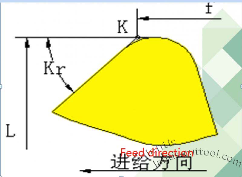
The position of the reference point K for the different principal declination angles KR and
Feed Direction, according to the following three diagrams.
1. For the outer circle or imitation with the main deflection angle kr less than or equal to 90°
EXCIRCLE or imitation Form turning tool shape, reference point K position according to below figure 1.
2. End cars with the main deflection angle kr less than or equal to 90°
Knife, Reference Point K position, as shown in below figure 2.
3. For the principal declination KR greater than 90°
Cylindrical, end-face or profile turning tools, reference
Click figure 3 FOR THE LOCATION OF POINT K.

[…] Metal Cutting pm2:00 […]